INSIDE
RACING
T E C H N O L O G Y
IRT Home
News Page
Contents Page
Newsletter &
Books
email Paul
Nazareth Photos by Mark Kohler
Mark Kohler is a subscriber of my newsletter, TV MOTORSPORTS, and a race fan. We tried to hook up at Nazareth but kept missing each other. He knows the Nazareth area and prior to the race he sent me a list of local restaurants that proved valuable. Later Mark emailed some photos that are technically interesting.
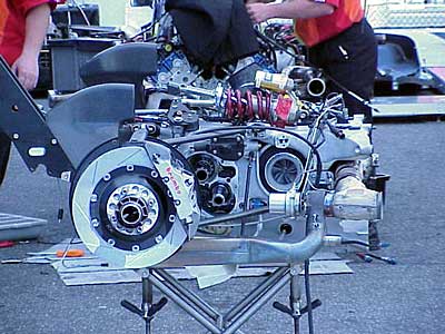
Mark was interested in the brakes when he took this shot but he got some other interesting stuff. I'm not sure what team this is but this part is the complete transaxle--the gearbox, rear axle and suspension, differential, turbocharger and wastegates. The team is making an engine change, that's an engine under cover at the rear. The rear shocks and springs sit on top of this assembly. All this bolts to the rear of the engine and all the loads from the rear of the car go through that connection to the rear of the carbon-fiber chassis. This assembly has to be very stiff and easy to work on so engine changes can be done quickly.
Starting from the left that's the rear wing support going up diagonally to the left. Then you see the brake scoops (they had to brake hard for Turn 3 running speedway wings) and brake rotors with Brembo calipers. Just to the right of the caliper are the ends of the gear shafts in the transverse gearbox. Next to the right, that shiny can is the right-hand wastegate that controls how much exhaust pressure gets to the turbocharger. The headers from the engine connect to that coupling you see at the far right. The wasted gases exhaust into that pipe at the bottom that comes our way and turns to the rear. All this exhaust plumbing is duplicated on the other side.
Just above the wastegate you can see the compressor-inlet side of the turbocharger. Honda, Cosworth/Ford and, I think, Toyota inject some fuel before the compressor. Ilmor, manufacturer of the Mercedes-Benz engine does not do this and I think it's one reason why they are not quite as powerful or as drivable as the Honda and Cosworth engines.
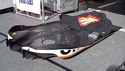
Mark took this photo of the underwing of Herta's Reynard. The Shell-logo blanket covers the diffuser-end of the part. The end we can see is the inlet.
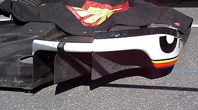
A close-up of the inlet shows the strakes that direct air out from under the car and also generate a vortex under the car that helps keep a boundary layer from forming. A thick, slow boundary layer can clog the flow at the diffuser lowering downforce and increasing drag. This inlet is a large volume where the air is at a relatively low speed. The area in the middle of this underwing is very close to the track when the car is at speed, so the air there is dragged up to the same speed as the car relative to the ground. As the air accelerates it looses pressure and the pressure difference between the air under the car and the air on top of the car presses it down.
CART rules say there has to be two inches difference between the bottom of the car and the bottom surface of the sidepods. You can see that here. Air flows from a higher pressure area to a lower pressure. Look at that inlet and imagine air sneaking under the lower edge of those strakes toward the lower pressure on the other side. The result is a clockwise corkscrew flow off each of these two strakes. The energy in that flow keeps the air attached to the underside of the car and helps keep slower, higher pressure air from leaking under the car and diluting the downforce.
Thanks, Mark!