INSIDE
RACING
T E C H N O L O G Y
IRT Home
IRT Home
News Page
Contents Page
Newsletter &
Books
email Paul
BAR Aero Details
Back to the USGP Start Page.
While Steve Matchett prepared for and recorded his taped walkaround of the BAR F1 car I took almost a roll of film. The flat black carbon fiber materials don't show up well in some photos. Maybe if I were a better photog!
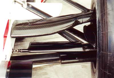
I was surprised by the sculpted shapes of the front suspension links. The changes in cross section are dictated by the rules in some cases.
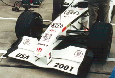
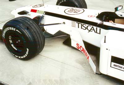
The rules change that raised the front wings has resulted in higher angles of attack for the front airfoils and more plan-view area to prevent loss of downforce at the front.
I think that projection on the side of the nose is an on-board TV camera.
The front wing end plate does many jobs. The bottom extension seals the underside. The vortex generator adds downforce and creates turbulence that helps reduce tire drag and lift.
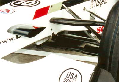
This view shows the pylon under the nose where the lower control arms attach to the tub.
Would you look at that? They've obviously got a lot of people and money. Having said that, these components influence the air flow over them which then flows over everything downstream. The goal is low drag, max downforce, and good flow into the cooling ducting. Hundreds of hours in the wind tunnel fine tunes the shapes of all this stuff.
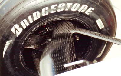
That's the pitot tube on the nose just out of focus at the bottom of the photo. Again notice the careful scupting of these components, obviously all made from carbon fiber reinforced plastic or CFRP. The spots of color inside the wheel are electrical connectors for sensors, temperature and speed sensors I'd guess. I would expect a bigger duct for air to the brakes but maybe they're using a fan inside to pump cooling air.
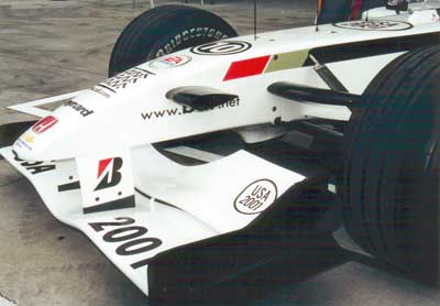
This is another critical area for airflow management. Notice the horizontal plane between the suspension links. The black thing under the nose is the splitter, so called because it splits the air into that going under the car and that going around the car. The vertical vane with Sonix on it is called a barge board. Air flows from high pressure areas toward low pressure. When the car is moving from the front of the barge board to the back side. Air also wants to flow along the length of the BB. So air spills over the top and bottom edges generating swirls of air,
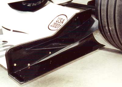
Another view of the barge board showing how the front edge is sculpted.
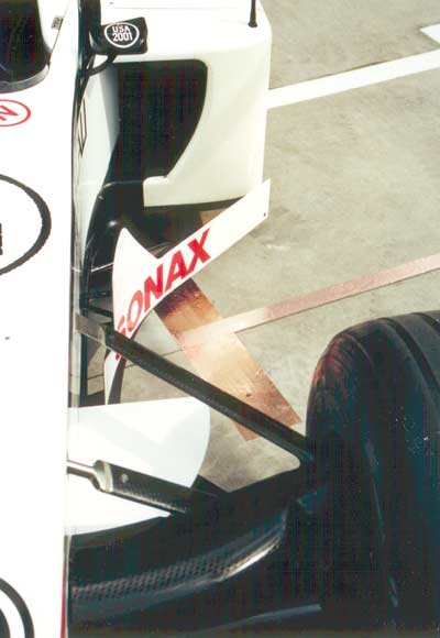
This view gives you a good look at the airflow path from the front suspension links over the dive plane, around the barge board and then either under the car, around the sidepod, or into the cooling duct. Notice the metal ends on the pushrod. I assume those are machined from Titanium. CFRP is very stiff and strong but brittle so areas of high loading, like the ends of the links, need to be metal. The teams have become very skilled at making screwed and bonded CFRP-to-metal attachments. Finally, that copper strip is there to electrically ground the car when it comes in for a pit stop preventing sparks that could start a fire.
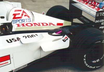
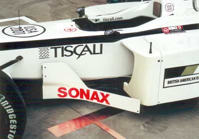
Those two aero doo-dads on the sidepod generate flows that help L/D by influencing flows to the rear wing and over the rear tires. That purple thing is a cover for the engine exhaust in the top of the sidepod. The rear wing is a three-plane design and the top plane is dual-airfoil.
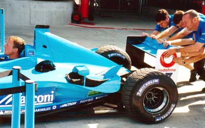
For comparison look at the Benetton engine cover and notice how much lower it is than the BAR. That's a result of the new wide-angle V-10 produced by Renault. As a result the rear wing might get less turbulent flow work more efficiently. A lower center of gravity might be another benefit. Compare the aero tweaks at the rear of the sidepod with the BAR. The rear wing looks to be two-plane with the top dual-plane.
I asked an aero guy why the aero tweaks are so different on all the cars. "The air's the same isn't it," I said. "And the wind tunnel's can't be that different." He told me each car is an aero system and small changes effect everything around that change. Aerodynamicists have different models in their heads about how the air flows around the cars and what effects changes have. So, as a basic design develops the details can diverge from similar designs done by different people.
The following explanation is incorrect. [Also notice the small hole in the side of the airbox behind the drivers head. That's required by the rules and prevents a power increase caused by higher pressure engine inlet air due to ram effect at speed. The hole just bleeds the higher pressure out of the air box.]
After I posted this page Ben Mitchell of technicalf1.com sent me a message saying this hole was a requirement for emergency lifting of the car. I checked the FIA rules and he's right. I thought I had read about a hole for pressure equalization but I guess not. Thanks, Ben!